Relevant Skills
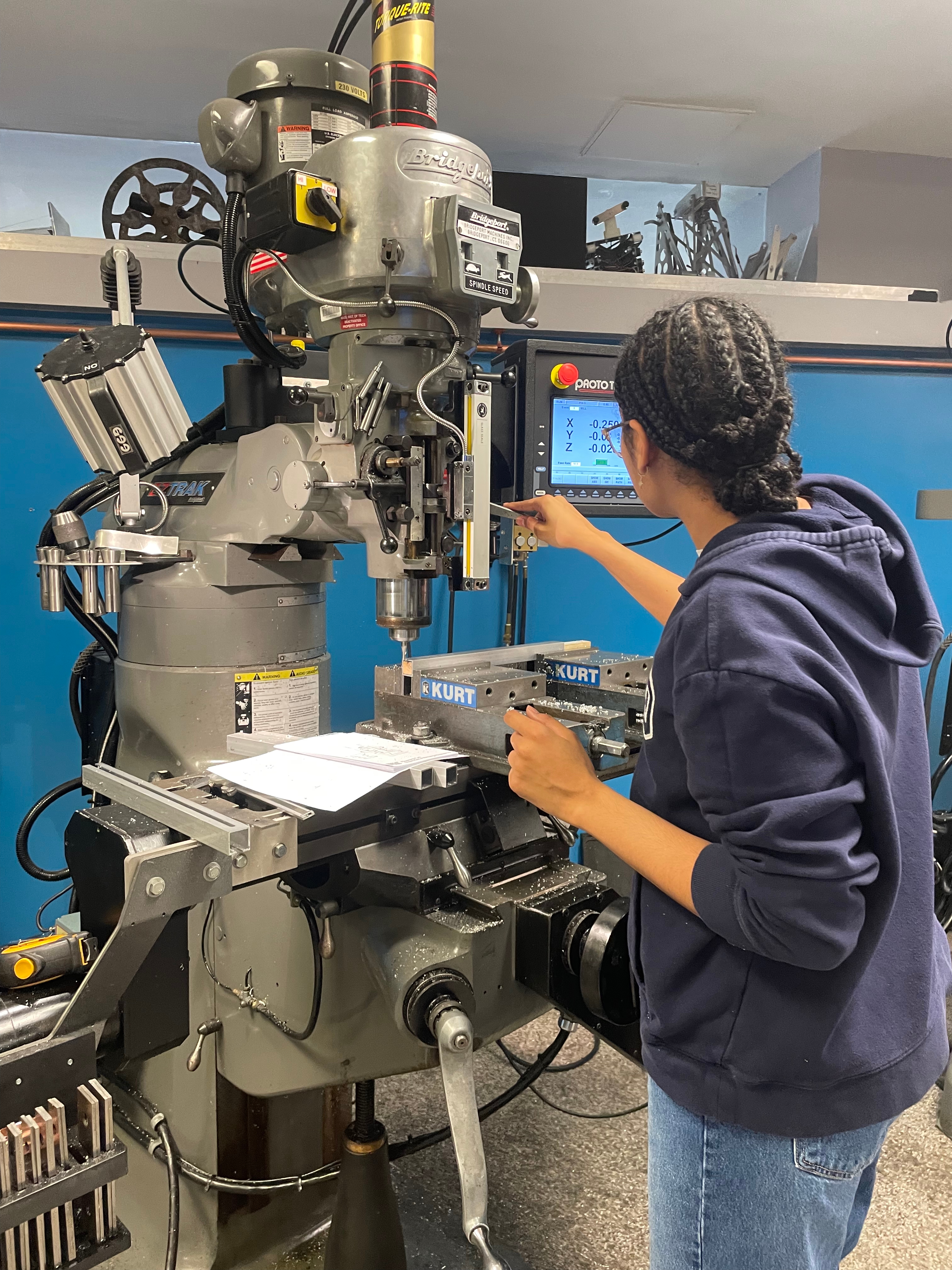
Manual Mill
Manual Lathe
SolidWorks
Engineering Drawings
Rapid Prototyping
Project Summary
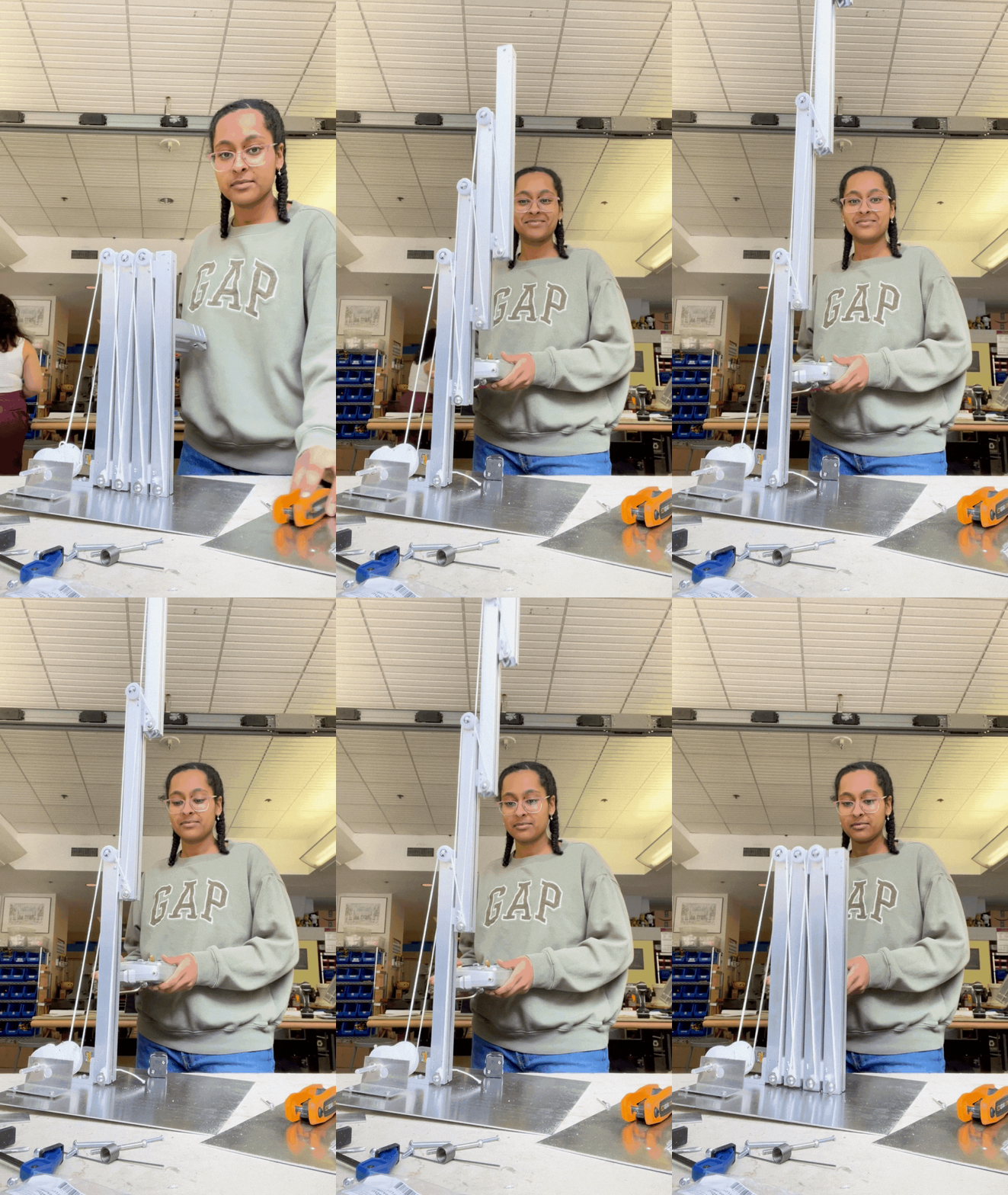
Built for MITs 2.007 (design and manufacturing I), and awarded the International Design Competition award. The robot consists of a telescoping arm mechanism, a spring-loaded deploying arm, and a motorized claw. All of this is integrated on a weighted chassis with two wheel drive, and is fully remote controlled.
Class Requirement: Must submit a robot that is capable of scoring points.
My Requirements Submit and compete with a robot that is capable of completing the highest scoring task - collecting Elphaba's broom from a 51″ tall platform.
Gameboard and Strategy
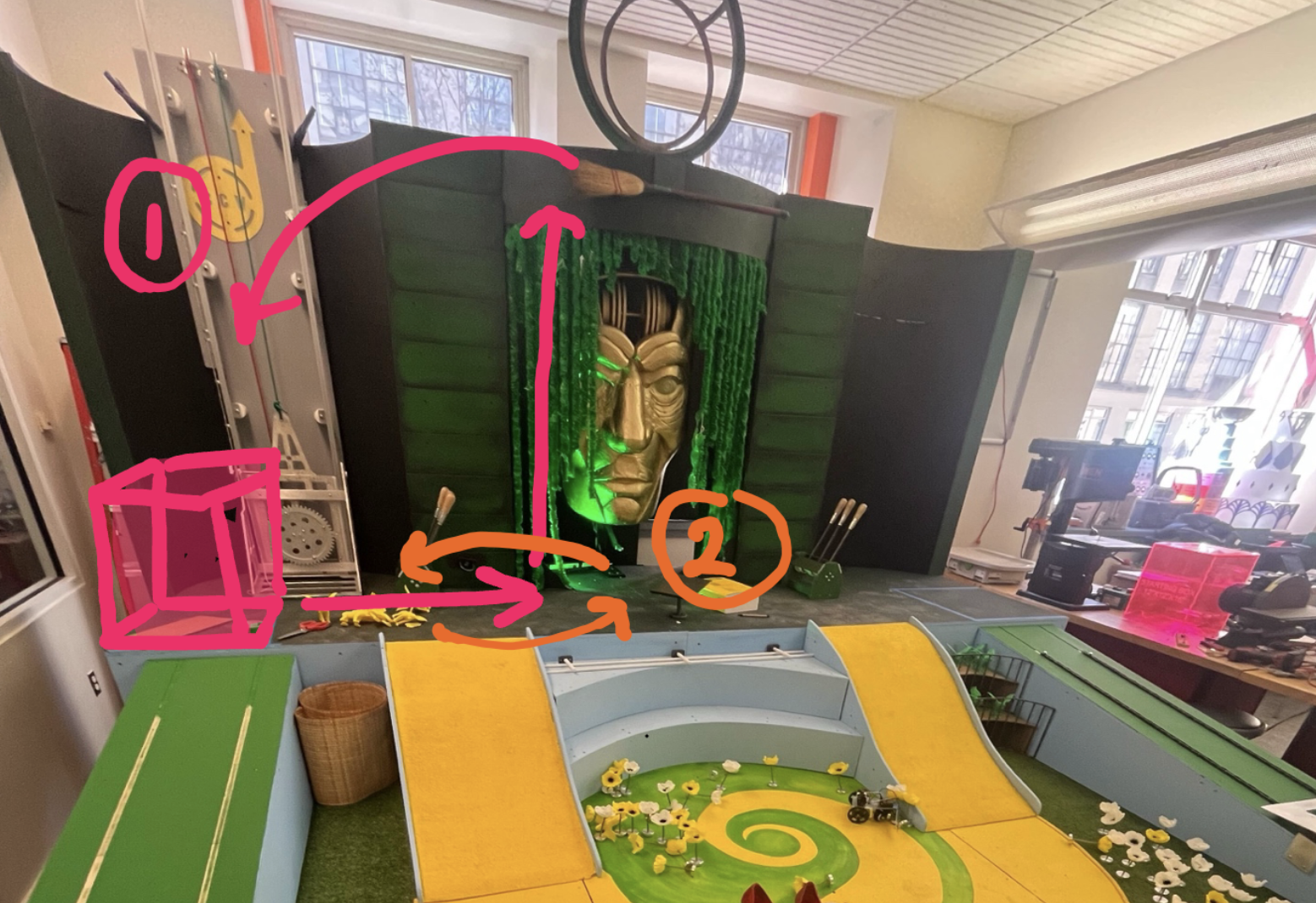
The game board was "Wicked" themed, and my strategy was to grab the broom (step 1) and apply the 2x multiplier (step 2), which would be an interesting design challenge as well as a high scoring strategy at 300 points.
I broke down my robot into key modules:
- Drive
- Reach (most critical module)
- Grab
Reach: Developing the Most Critical Module
I spent some time loosely exploring the design space and using foam core to model the basic functionality of different mechanisms. Here are some design journal entries:
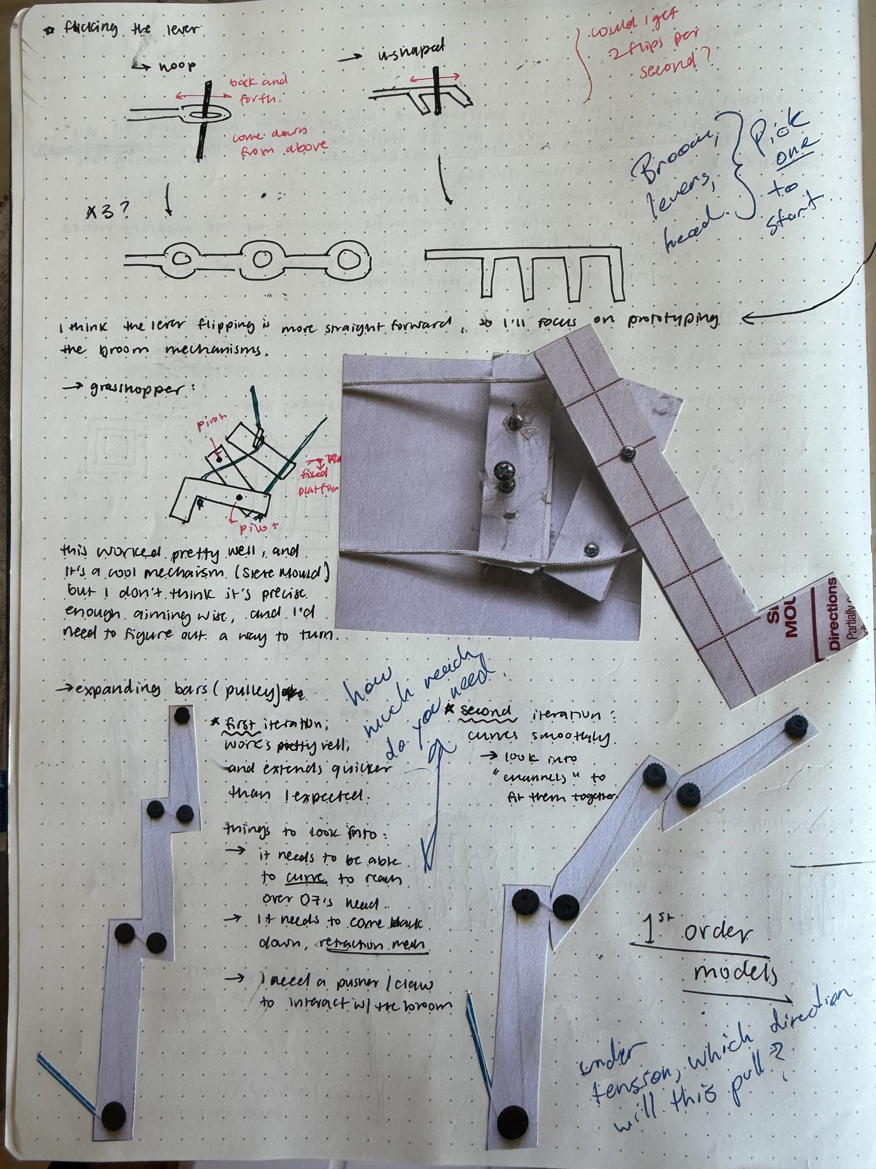
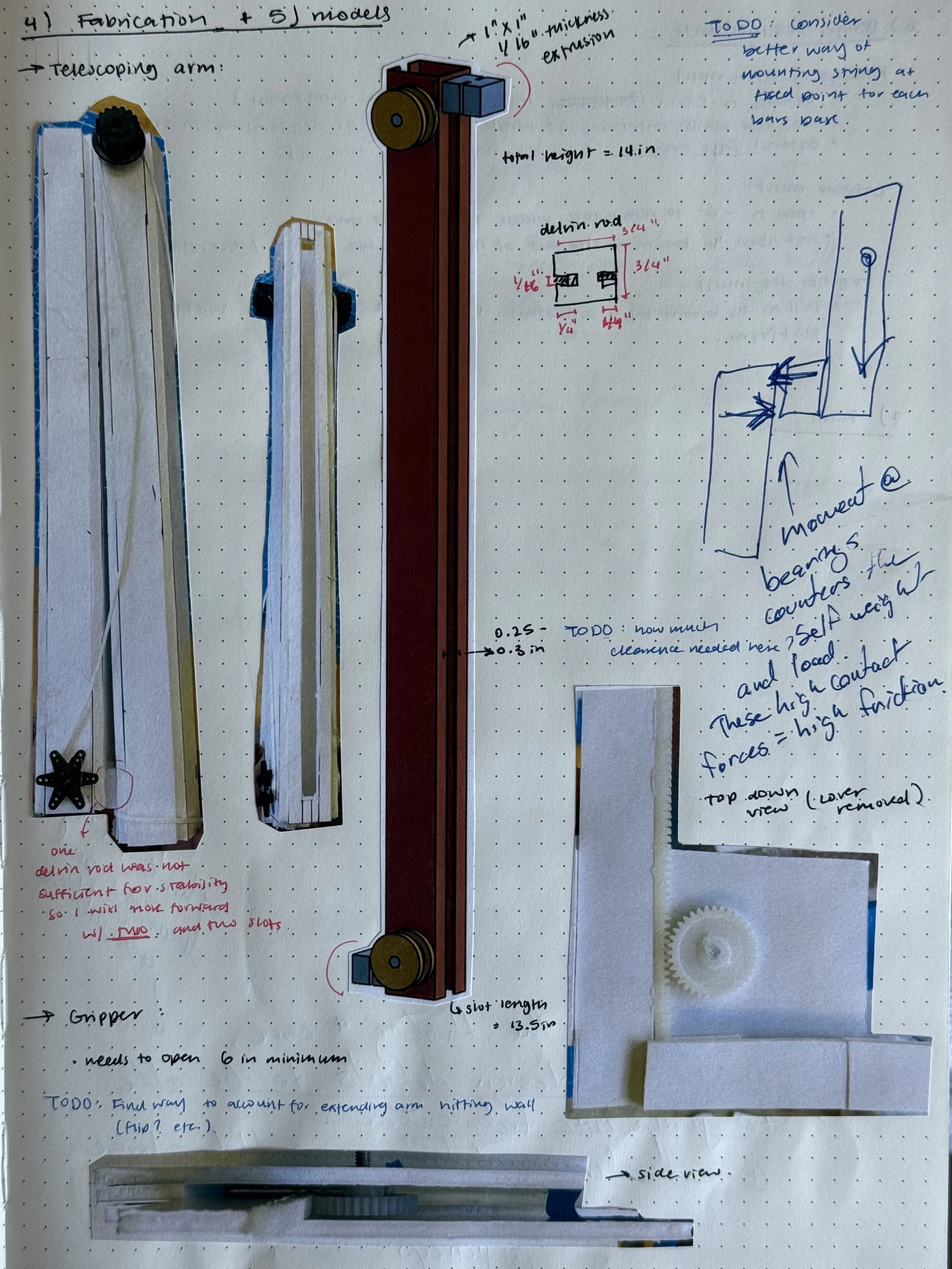
I came to a few conclusions
- A telescoping arm mechanism is likely the most compact extension method I can reliably machine within the classes material limitations.
- The broom being the highest scoring task, it is not unlikely I will need to compete agains someone who is also aiming for it, so a claw at the end of my extension system will give me strength and dexterity in competition which could make or break a game.
- I need to be very aware of stability since my robot is extending 51″
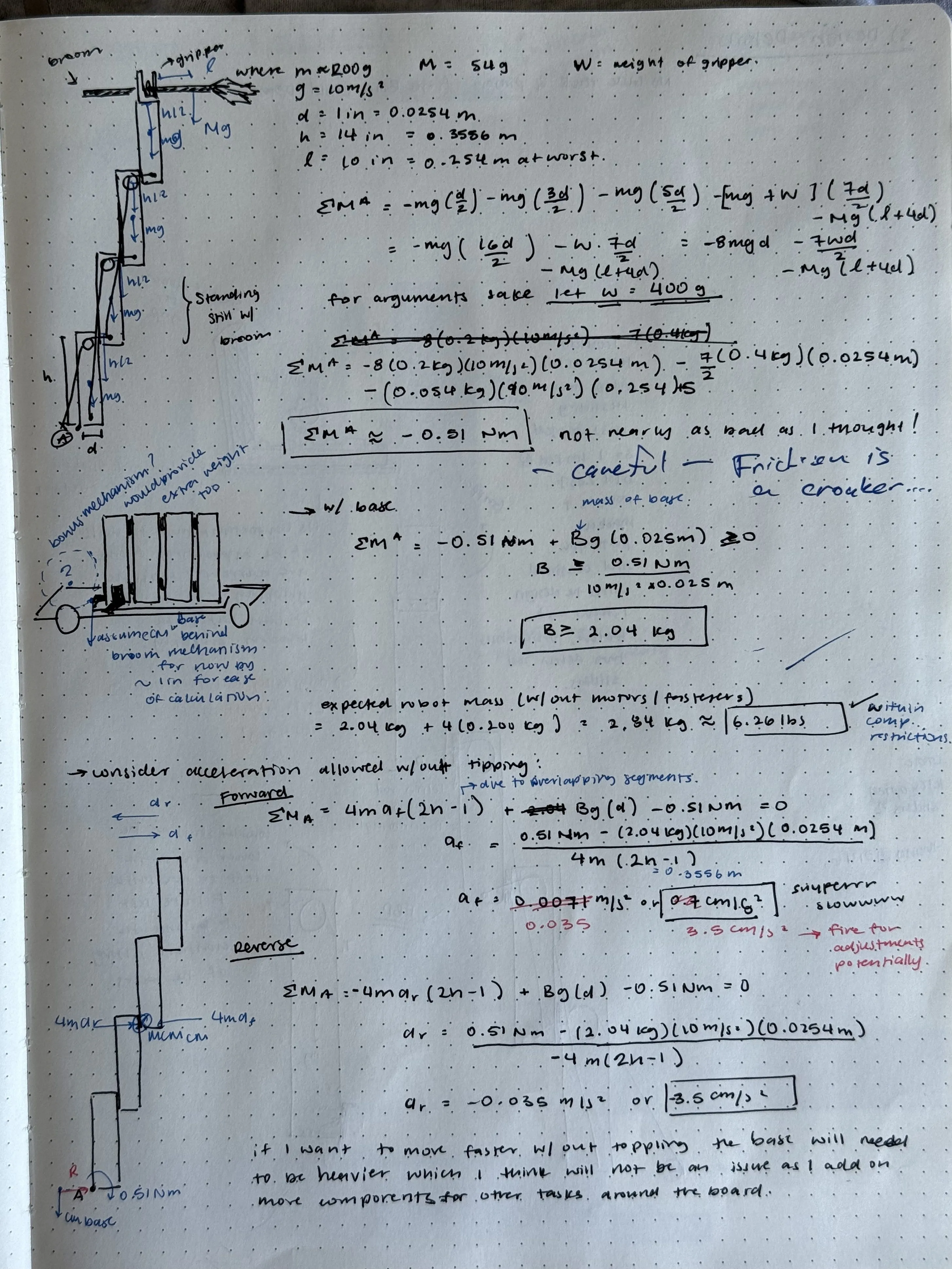
My calculations here show that I need a total robot mass of 6.26 lbs to prevent tipping, which is half the allowable robot mass
With these calculations in mind, I can machine a four arm telescoping system, and would need to deploy the claw separately to stay within the height limit.
with these in mind I moved onto fabrication
Grab: Developing the Claw Module

The claw is intended to give me a more controlled descent once I am in contact with the broom, the basis of the mechanism is a pair of linkages driven by a single motor.
I used a sketch in CAD with one degree of freedom to determine the lengths I would use for each of the links
This will be laser cut out of aluminum sheet metal, and each piece will consist of two layers riveted together increase thickness and rigidity.

and in sheet metal...

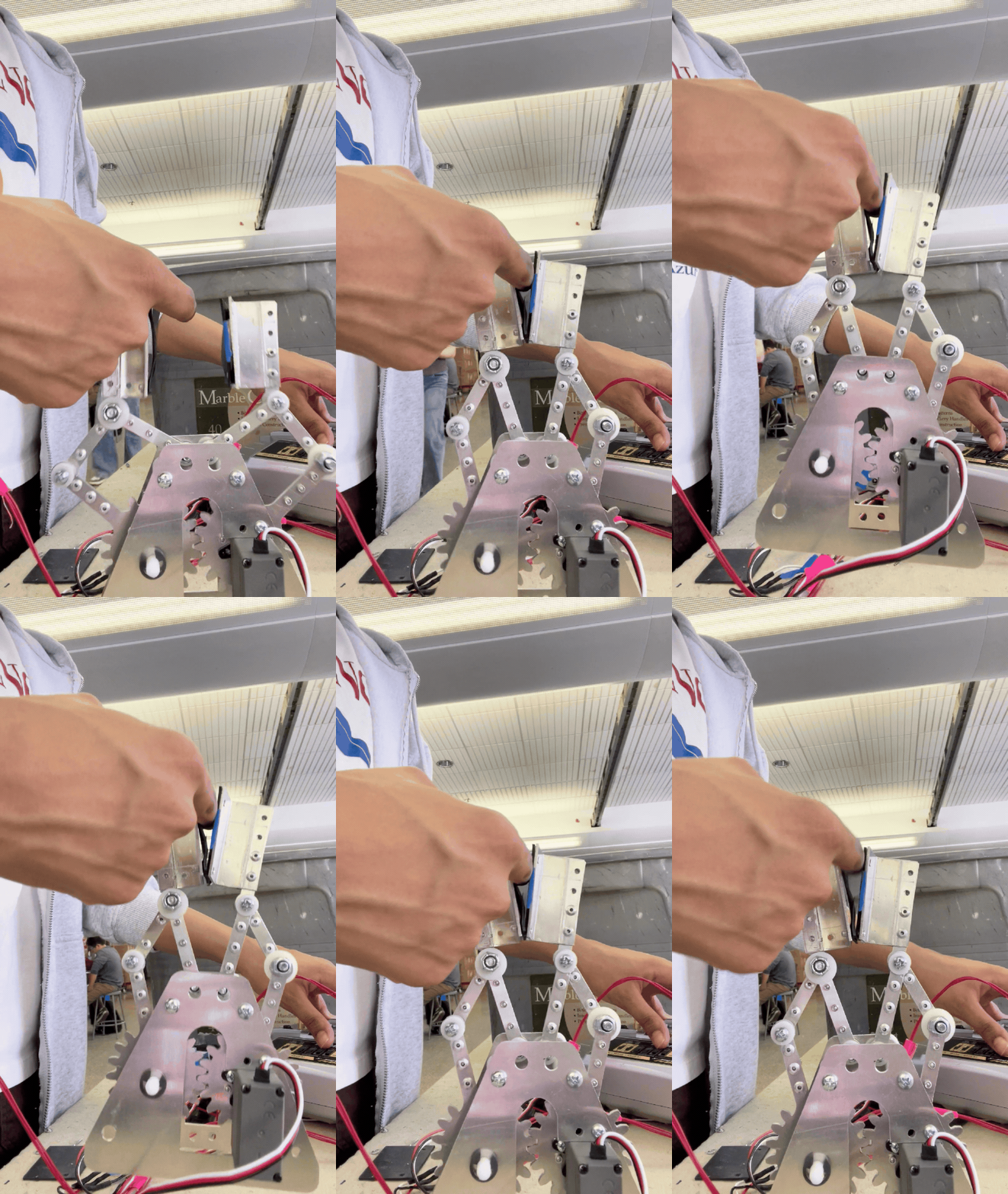
First and second iterations of the claw.
On the second edition I widened the contact surface area and added a rubber sheet for improved grip.
I ended up manufacturing another claw with better tolerances and slightly tighter joints to get rid of some the shifting it was experiencing before. But more on that later!
Drive: Drive Motors and Chassis
I want to minimize inefficiencies in the motors, so I need to ensure they don’t experience any unnecessaryradial forces. In this case I couldn’t simply support the wheels due to space limitations, the next best thing was to use Saint-Venant’s principle to determine how far away I should position the motors, shaft support, and wheel.
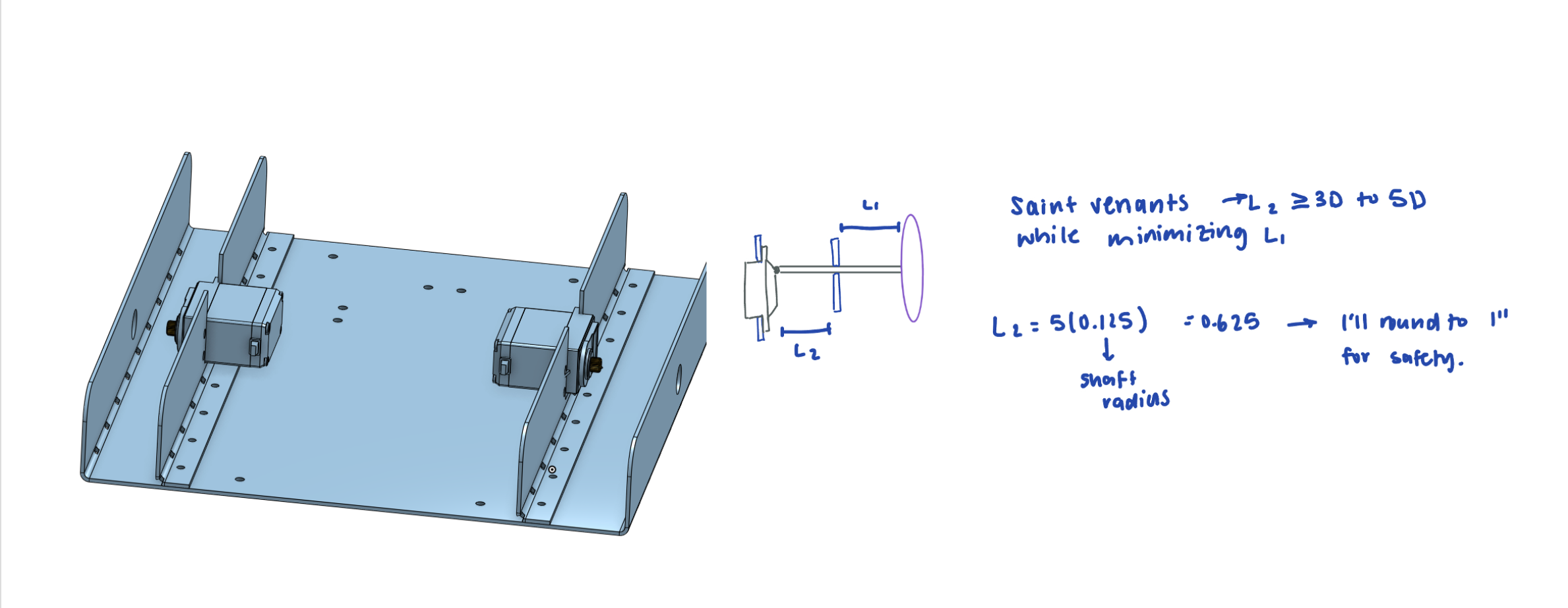
The body was also metal laser cut, bent, and riveted together.
Assembly and Refinement
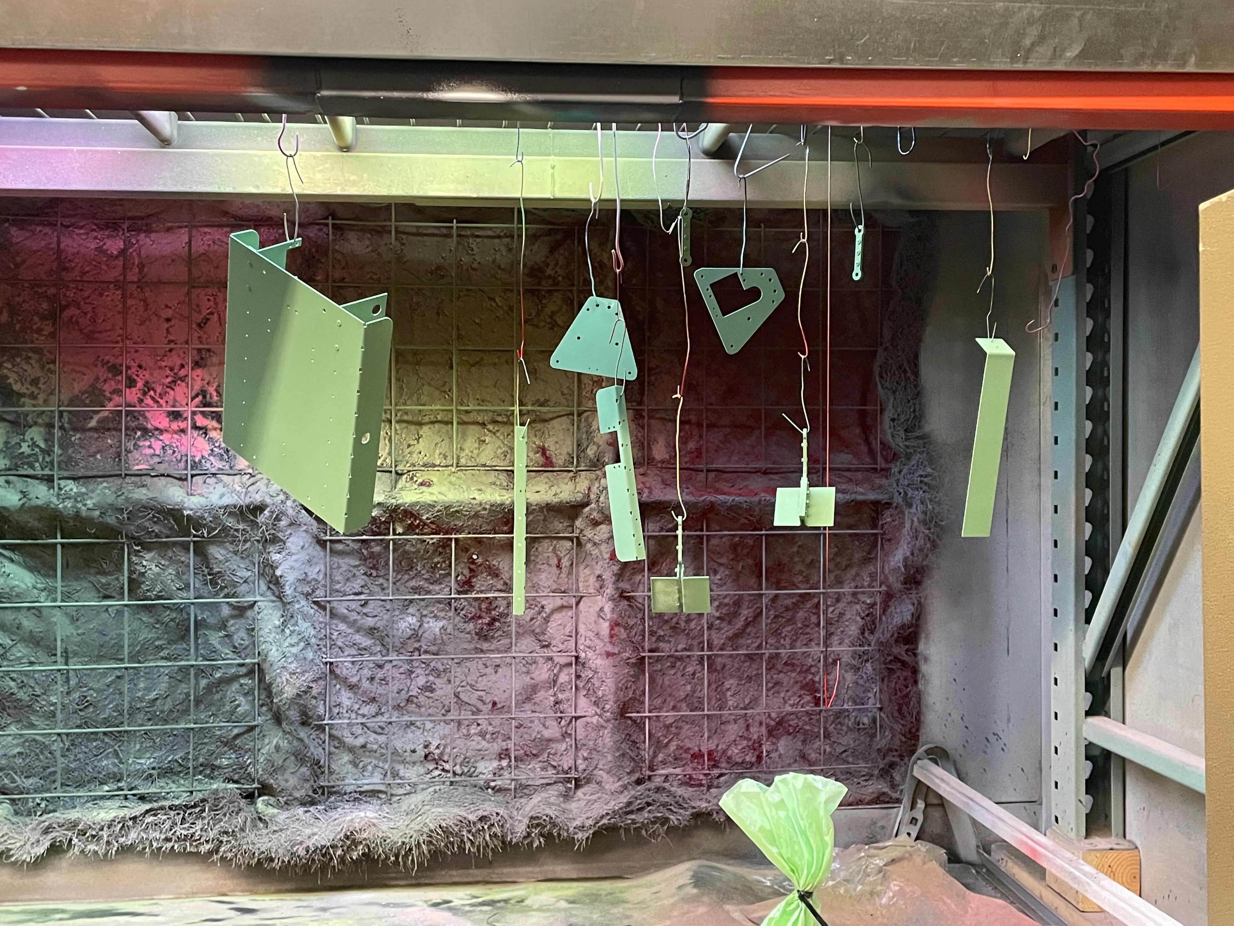
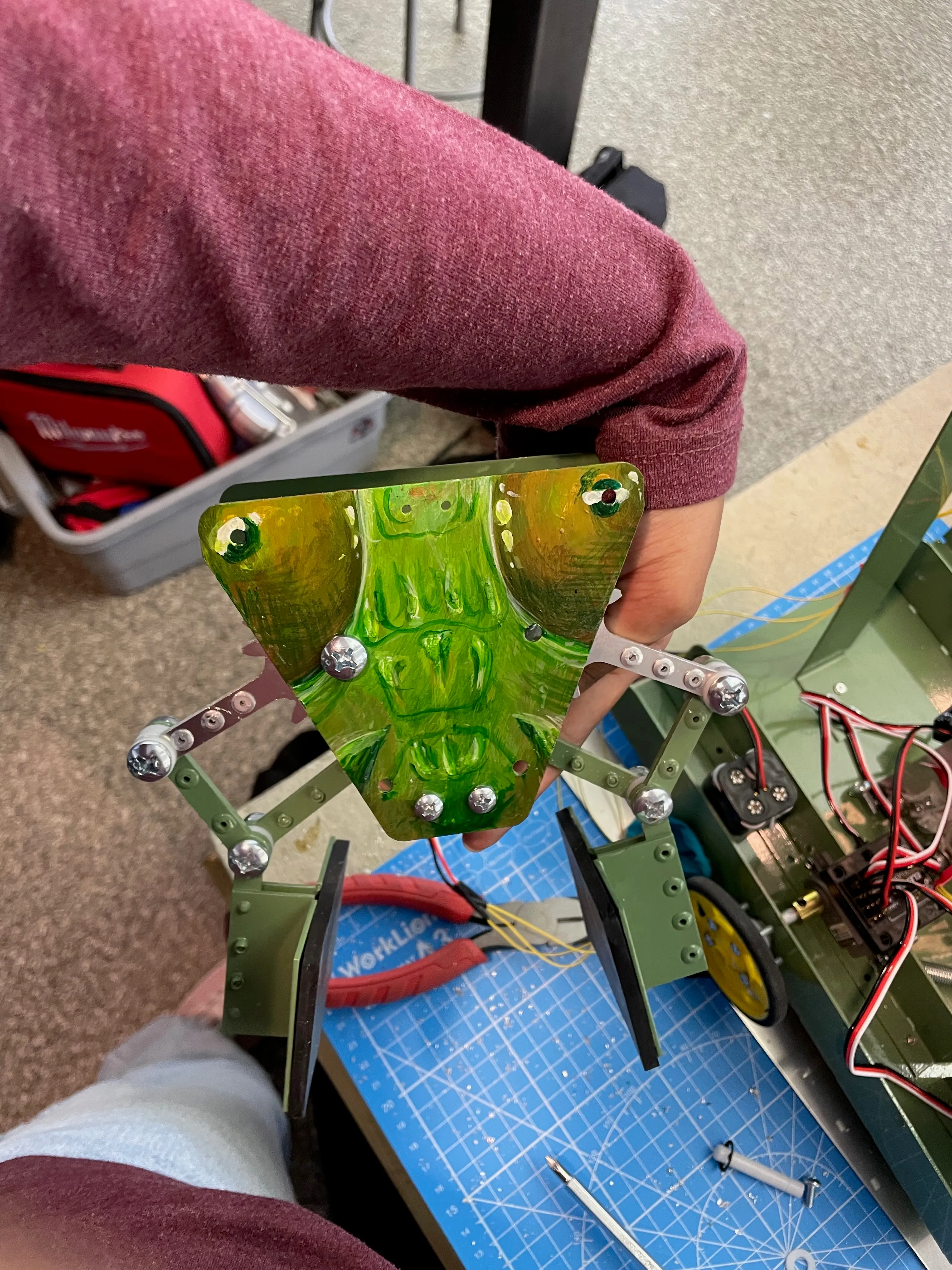
Powder coated the chassis and claw linkage and painted a grasshopper face on the front of the claw (a nod to one of my original ideas). As competition day drew closer I named my robot “Wicked Taahl” I proceeded with some wire management and practicing my driving skills.
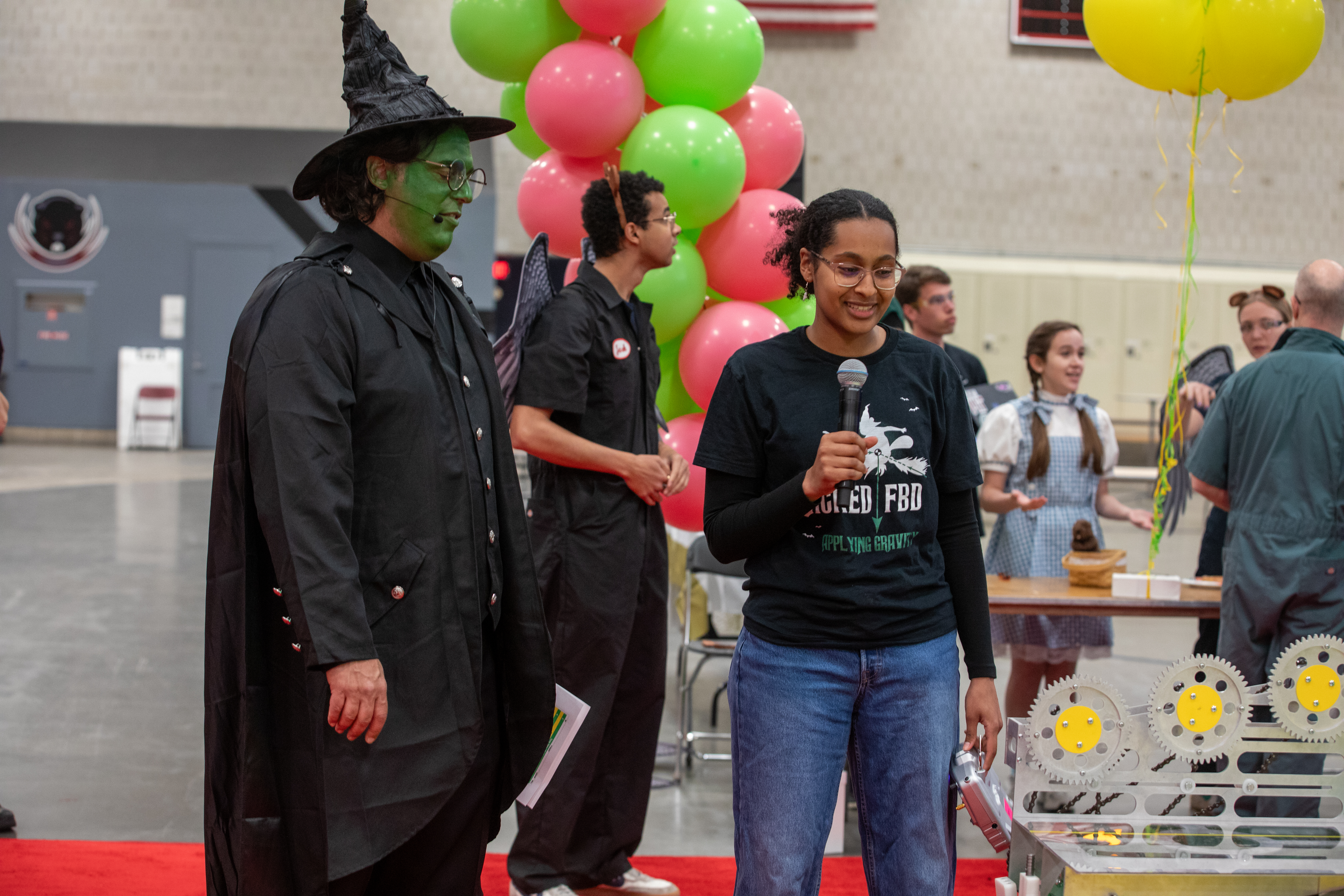
Competition Day!
Takeaways and Final Thoughts
This build experience has been so incredibly formative for me. I learned how to justify my design choices with mathematical analysis, become proficient on the mill and lathe, and understand the importance of design within the constraint of manufacturing capabilities. I strengthened my ability to ideate and take a wide range of potential solutions into consideration as I saw my robot come to life!